In ATX Version 3 Multi Rail Desktop Platform Power Supply Design Guide 2.1a, Intel groups the auxiliary power connectors used by PCI Express Add-in Card devices into three categories:
PCIe 2x3PCIe 2x412V-2x6
In practice, the most common Add-in Card here is a discrete graphics card. The document also makes it clear that these connector types cover a power range from 75W all the way up to 600W.
1. The short version first
If you only want the key distinction, you can think of them like this:
2x3corresponds to the familiar GPU6-pin, rated for75W2x4corresponds to the common GPU8-pin, rated for150W, and backward-compatible with2x312V-2x6is the newer high-power GPU connector, with support up to600W
The real dividing line is not just wattage, but also this:
2x3 / 2x4still follow the traditional auxiliary power approach12V-2x6folds high-power delivery, insertion-state detection, and sideband signaling into the standard itself
2. PCIe 2x3: the old 6-pin, defined here as 75W
On this page, Intel defines the 2x3 Auxiliary Power Connector as an auxiliary power connector that can provide 75W for a PCIe add-in card.
The key details include:
- The design target is
75W - The maximum rated value is
8.0A/pin - The cable gauge listed is
18 AWG - One
Sensepin needs to be tied to ground so the graphics card can detect whether a2x3auxiliary power cable is connected
If you map it to today’s PC-building terminology, this is essentially the familiar GPU 6-pin auxiliary power connector.
3. PCIe 2x4: 8-pin, 150W, and backward-compatible with 2x3
The 2x4 Auxiliary Power Connector corresponds to the more common GPU 8-pin connector, and Intel gives it a target power level of 150W.
There are two especially important design points here:
- A board-side
2x4receptacle can accept either a2x4plug or a2x3plug - The graphics card uses
SENSE0andSENSE1to identify which type of cable is actually plugged in
Intel gives the following detection logic:
SENSE1 |
SENSE0 |
Meaning |
|---|---|---|
| Ground | Ground | A 2x4 plug is inserted, so the graphics card may draw 150W from the auxiliary connector |
| Open | Ground | A 2x3 plug is inserted, so the graphics card may draw only 75W |
| Ground | Open | Reserved |
| Open | Open | No auxiliary power cable is connected |
So a board-side 8-pin is not simply “a 6-pin with two extra pins.” It also carries the power-identification logic.
4. 12V-2x6: the new high-power connector, up to 600W
With 12V-2x6, the positioning changes completely. Intel directly defines it as a 12V power connector for PCIe add-in cards that can deliver up to 600W.
The main points in the document include:
12V-2x6is not compatible with2x3or2x4- Its primary power-contact pitch is
3.0 mm - The contact pitch of
2x3and2x4is larger at4.2 mm - This connector uses
12large contacts for power delivery, plus4smaller contacts for sideband signals
Its cable requirements are also stricter than those of older connectors:
- Power and ground wires use
16 AWG - All
12main power pins must be fully wired, with no missing conductors - Sideband signal wires use
28 AWG - The main power pins are rated at
9.2A/pin
The document also requires an H++ marking on the connector body to indicate support for 9.2A/pin or higher.
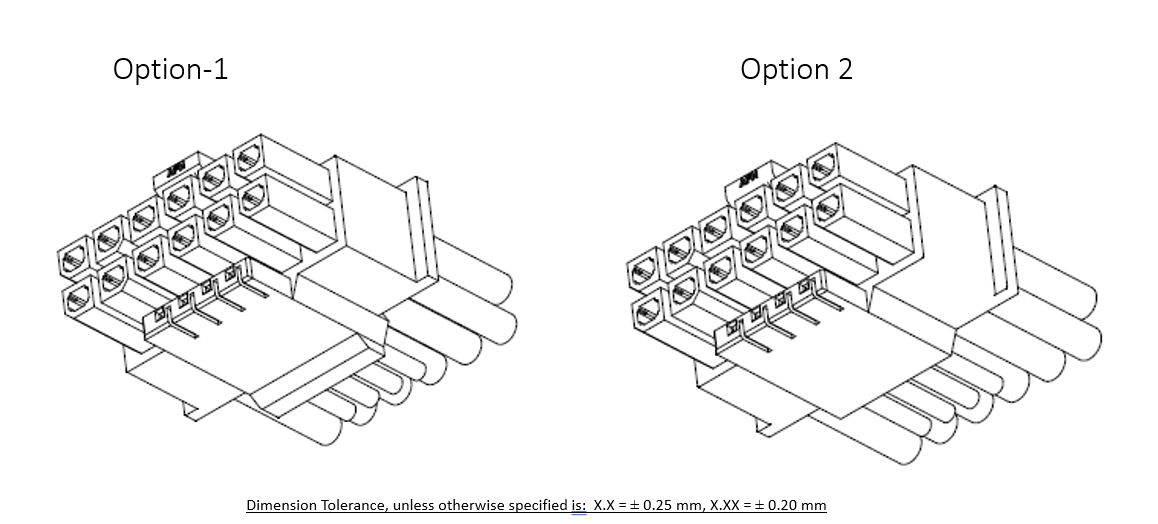
The image above is Figure 5-3 on Intel’s page, corresponding to the 12V-2x6 Cable Plug Connector.
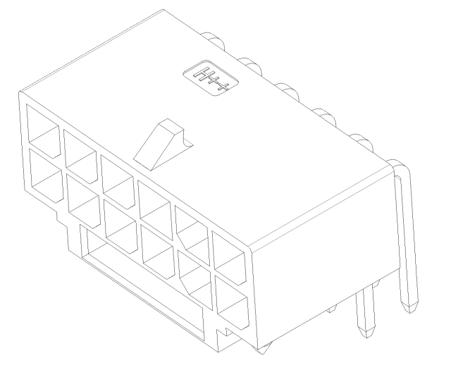
This one is Figure 5-5, corresponding to the 12V-2x6 PCB Header. Looking at the two diagrams together, it becomes much easier to see that this is no longer the traditional 6-pin/8-pin connector form.
5. Why 12V-2x6 is not the same as the early 12VHPWR
Intel includes a dedicated section in this guide called 12V-2x6 vs. 12VHPWR.
Its conclusion is very clear:
- Early
12VHPWRhas been deprecated PCIe CEM 5.1switched to12V-2x6- The two look broadly similar, but the newer connector adds several reliability improvements
The core changes mainly fall into two groups.
The first is mechanical structure:
- The main power pins are longer
- The sideband pins are shorter
The goal is to let the main power pins make contact first and break contact last, while the sideband signals only connect after the main power pins have been inserted deeply enough.
The second group is updated SENSE0 / SENSE1 logic:
- The
150Wlevel now requiresSENSE0andSENSE1to be shorted together - When both signals are in the
Open-Openstate, the new spec defines that as0W - In other words, if the plug is not fully inserted, or not inserted at all, a compliant graphics card should not draw power from that cable
That is also one of the reasons 12V-2x6 is considered more conservative and more robust than the early 12VHPWR.
6. What do the four 12V-2x6 sideband signals do?
On the sideband-signal page, Intel defines four signals for 12V-2x6:
SENSE0, requiredSENSE1, requiredCARD_PWR_STABLE, optionalCARD_CBL_PRES#, required on the graphics-card side and optional on the power-supply side
1. SENSE0 / SENSE1
These two signals tell the graphics card what power level the cable and power supply currently allow.
Intel provides the following power table:
SENSE0 |
SENSE1 |
Initial allowed power at startup | Maximum sustained power after software configuration |
|---|---|---|---|
| Ground | Ground | 375W |
600W |
| Open | Ground | 225W |
450W |
| Ground | Open | 150W |
300W |
| Short | Short | 100W |
150W |
| Open | Open | 0W |
0W |
The key is not memorizing the table, but understanding this: 12V-2x6 is no longer just a binary “power/no power” connector. Through sideband signals, it explicitly encodes multiple power tiers to the graphics card.
2. CARD_PWR_STABLE
This is an optional signal, and it behaves a lot like a graphics-card feedback version of Power Good.
Intel defines it this way:
- When the graphics card’s local critical power rails are within normal range, this signal stays open/high impedance
- When the graphics card detects that those local critical rails are out of range, it actively pulls the signal low
- If this signal is implemented, the power-supply side should pull it up to
+3.3Vthrough4.7 kOhm
Put simply, it gives the power supply an extra fault-awareness input.
3. CARD_CBL_PRES#
This signal is more about connection detection:
- It lets the power supply know that the
12V-2x6cable really is connected to the graphics card and seated properly - In a modular power-supply setup, it can also help confirm whether the PSU-side
12V-2x6cable is fully inserted
Intel also specifically notes that:
- The graphics-card side must implement the basic logic for this signal
- The graphics-card side should pull it down to ground through
4.7 kOhm - Monitoring this signal on the power-supply side is optional
It is not used to determine the allowed power level. That role still belongs to SENSE0 / SENSE1.
7. How to think about the relationship between these three generations of connectors
From a PC-building and connector-recognition perspective, you can simplify them into three generations:
2x3: the old6-pin, typically positioned at75W2x4: the old8-pin, typically positioned at150W, and backward-compatible with2x312V-2x6: the new high-power connector, up to600W
Going one step further:
2x3 / 2x4still follow the traditional auxiliary power-connector model12V-2x6standardizes high-power delivery, insertion state, and sideband communication together- The point of
12V-2x6is not just higher wattage, but also stricter insertion detection and clearer power-state encoding
Summary
From Intel’s ATX 3.0 design guide, PCIe auxiliary power connectors for graphics cards are already divided very clearly into three layers:
2x3corresponds to75W2x4corresponds to150W12V-2x6is aimed at up to600W
And the real difference between 12V-2x6 and the old 12VHPWR is not just the name or the appearance, but also:
- Updated mechanical structure for the main power pins and sideband pins
- Revised
SENSE0 / SENSE1encoding rules - The addition of the more conservative
Open-Open = 0Wstate - More complete connection and power-state handling through
CARD_PWR_STABLEandCARD_CBL_PRES#
If you are looking into high-power graphics cards, modular PSU cables, or simply trying to understand the relationship between 6-pin, 8-pin, and 12V-2x6, Intel’s official design guide already lays out the framework quite clearly.
Reference Links
- Intel EDC:
PCI-Express (PCIe*) Add-in Card Connectors (Recommended)https://edc.intel.com/content/www/us/en/design/ipla/software-development-platforms/client/platforms/alder-lake-desktop/atx-version-3-0-multi-rail-desktop-platform-power-supply-design-guide/2.1a/pci-express-pcie-add-in-card-connectors-recommended/ - Intel EDC:
PCIe* Add-in Card 12V-2x6 Auxiliary Power Connector Sideband Signalshttps://edc.intel.com/content/www/us/en/design/ipla/software-development-platforms/client/platforms/alder-lake-desktop/atx-version-3-0-multi-rail-desktop-platform-power-supply-design-guide/2.1a/pcie-add-in-card-12v-2x6-auxiliary-power-connector-sideband-signals/ - Intel EDC:
SENSE0 & SENSE1 (Required)https://edc.intel.com/content/www/us/en/design/ipla/software-development-platforms/client/platforms/alder-lake-desktop/atx-version-3-0-multi-rail-desktop-platform-power-supply-design-guide/2.1a/sense0-amp-sense1-required/ - Intel EDC:
CARD_PWR_STABLE (Optional)https://edc.intel.com/content/www/us/en/design/ipla/software-development-platforms/client/platforms/alder-lake-desktop/atx-version-3-0-multi-rail-desktop-platform-power-supply-design-guide/2.1a/card-pwr-stable-optional/ - Intel EDC:
CARD_CBL_PRES# (Optional in Power Supply)https://edc.intel.com/content/www/us/en/design/ipla/software-development-platforms/client/platforms/alder-lake-desktop/atx-version-3-0-multi-rail-desktop-platform-power-supply-design-guide/2.1a/card-cbl-pres-optional-in-power-supply/ - Intel EDC:
Sideband Signals DC Specifications (Required)https://edc.intel.com/content/www/us/en/design/ipla/software-development-platforms/client/platforms/alder-lake-desktop/atx-version-3-0-multi-rail-desktop-platform-power-supply-design-guide/2.1a/sideband-signals-dc-specifications-required/