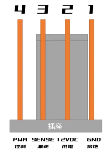
Pin Definitions
- Fan connector basics
Typical cooling fans use 3-pin or 4-pin connectors (common 2510 form factor).
A 4-pin fan can usually be connected to a 3-pin header with alignment.
-
4-pin fan connector
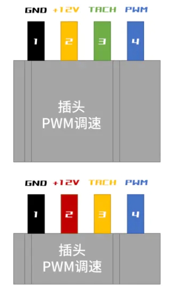
-
3-pin fan connector
FG / TACH Signal
TACH / FG is the fan speed feedback signal, usually output as pulses.
The motherboard estimates real-time RPM by counting FG pulses. The pulse count per revolution depends on fan design (for example 2 pulses/rev or 3 pulses/rev).
A common formula is:
- If pulses per revolution = 2, then
RPM = FG frequency * 30 - If pulses per revolution = 3, then
RPM = FG frequency * 20
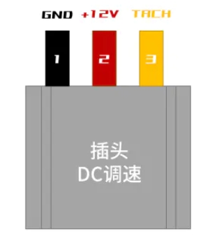
DC Speed Control
DC fan speed control is achieved by changing supply voltage.
PWM Speed Control
PWM Duty Cycle
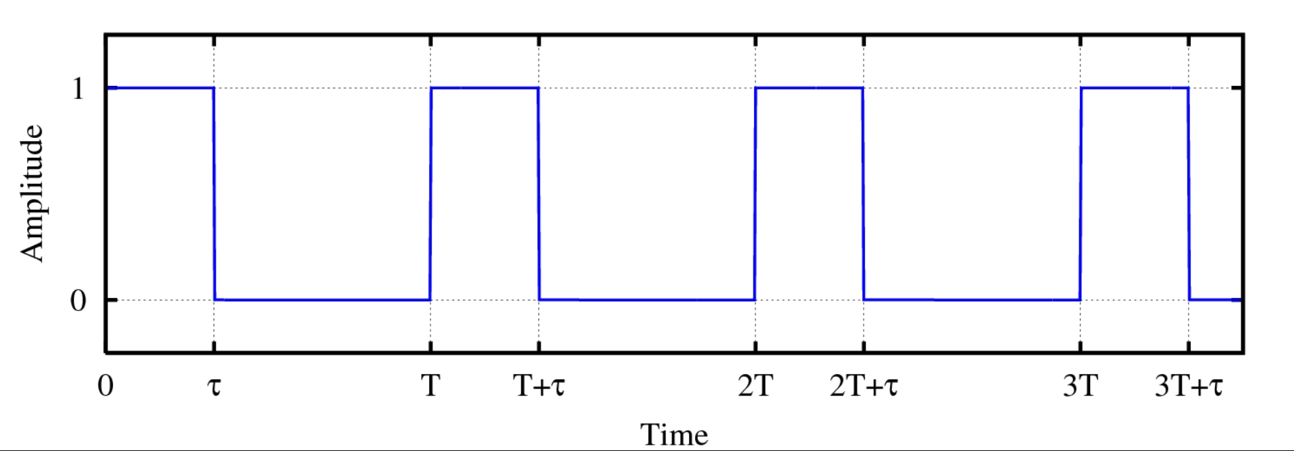
Duty cycle D is the ratio of high-level time t_on to period T.
PWM fan control adjusts speed by changing duty cycle:
- 100% duty: full speed
- 50% duty: roughly medium speed
- 0% duty: stop
PWM Frequency
PWM frequency is the switching frequency of the PWM signal (in Hz).
Common practical ranges:
- Low frequency: 1 kHz to 5 kHz (still usable on some older controllers)
- Typical range: 20 kHz to 30 kHz (common for many motherboards/fans)
- Higher frequency: >30 kHz (used in some designs, with different noise/efficiency trade-offs)
PWM Voltage Level
PWM amplitude is the voltage difference between high and low levels. Common logic levels are 3.3V or 5V, depending on fan/controller design.
Always verify the fan’s electrical requirements in the datasheet before final design.