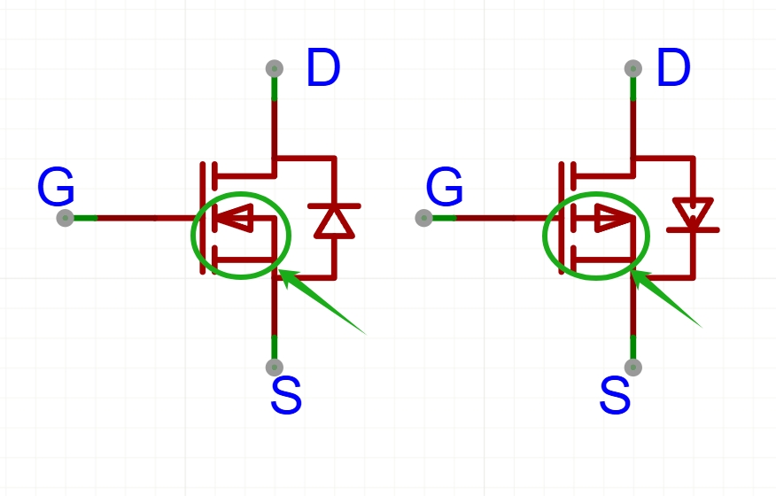
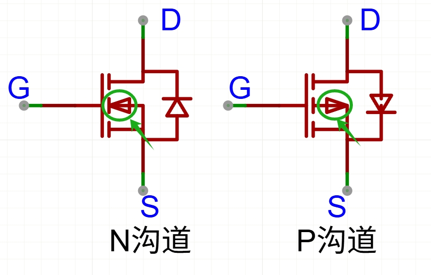
MOSFET Identification
Determining the Three Pins
G: Gate, the control terminal.
S: Source, one side where the P/N channel intersects.
D: Drain, the other side where the P/N channel intersects.
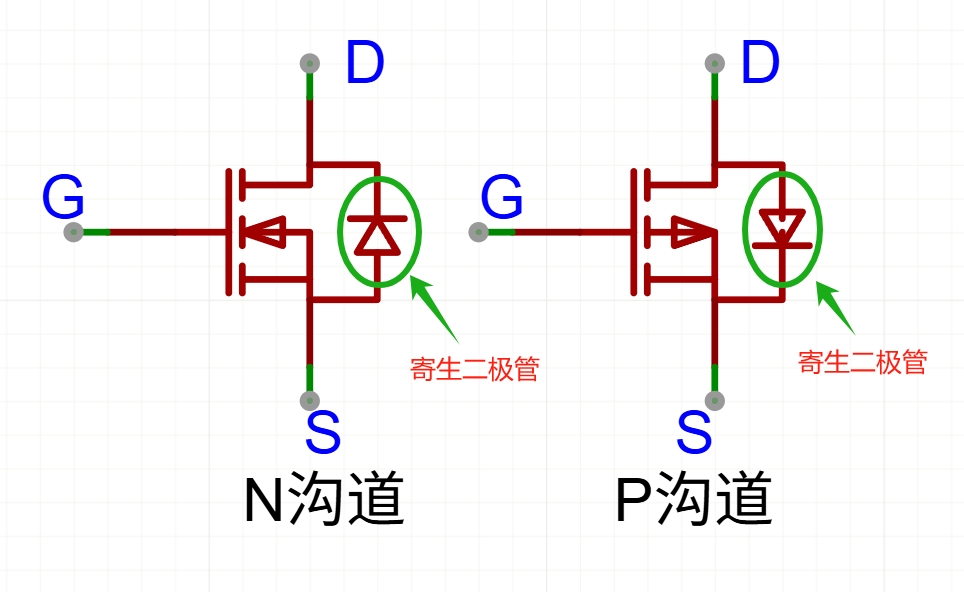
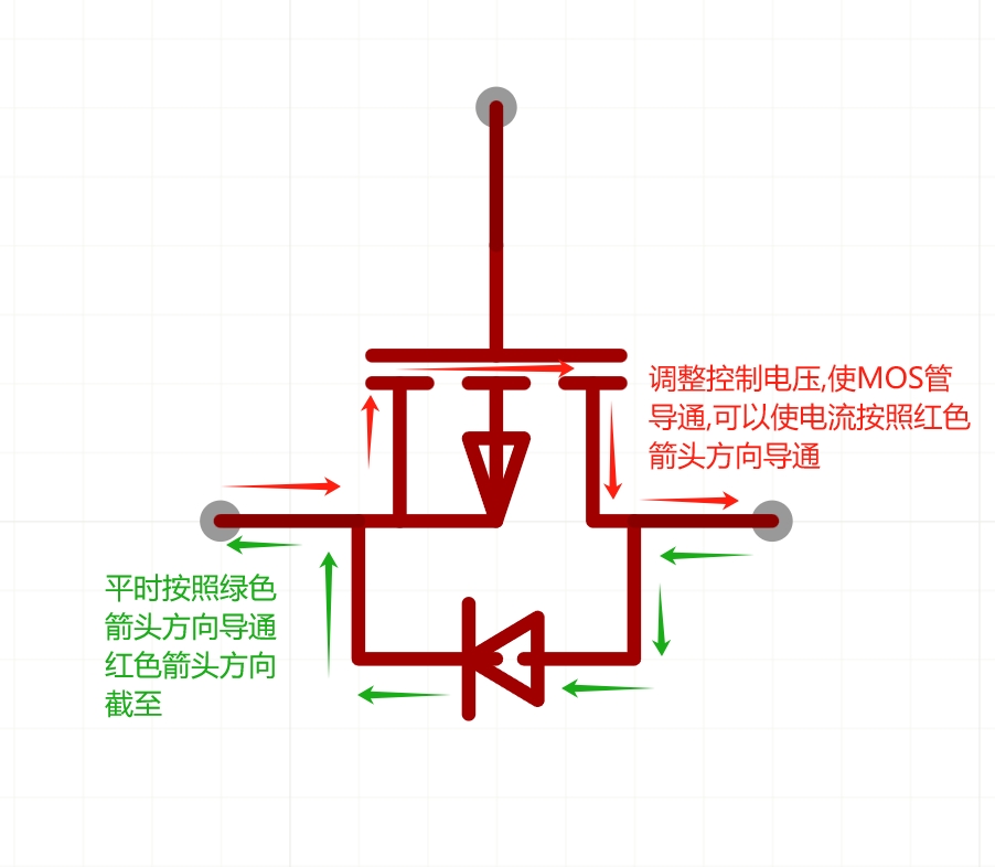
Built-in Body Diode Orientation
The body diode points from P to N:
for N-channel MOSFETs, the diode points from S to D;
for P-channel MOSFETs, it points from D to S.
For both N-channel and P-channel MOSFETs, the body diode direction is fixed, and this direction is important when selecting orientation in power paths.
Main MOSFET Applications
Switching Function
The most common use is switching: using a control signal to switch high/low levels, i.e., turn current flow on/off. The key is understanding gate drive conditions.
Turn-on rule:
For both N-channel and P-channel MOSFETs, compare UG (gate voltage) with US (source voltage).
N-channel: turns on when UG > US, and turns off when UG = US (or lower).
P-channel: turns on when UG < US, and turns off when UG = US (or higher).
A sufficient gate-source voltage difference is required to drive the MOSFET into full conduction.
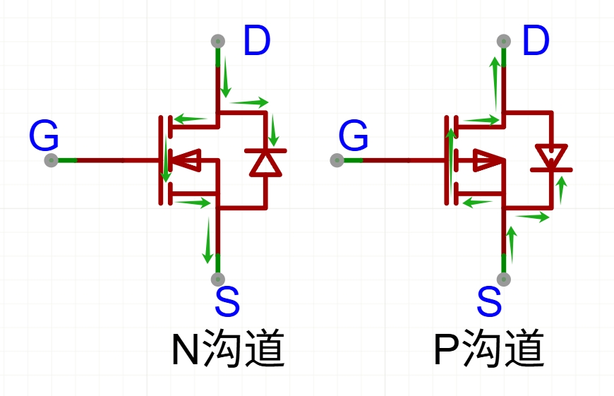
For N-channel vs P-channel MOSFETs, current direction in the on-state is opposite.
Reverse-Protection Function
In some circuits, only part of MOSFET behavior is used to implement reverse input protection. Compared with a diode, MOSFET-based reverse protection can reduce voltage drop and power loss when properly driven.
MOSFET Selection Summary
When using a MOSFET as a switch, N-channel and P-channel devices have different preferred high-side/low-side positions; choose according to drive voltage and reference potential.
When using a MOSFET for reverse protection, ensure the body-diode direction matches the intended forward current path.